Published 16th June, 2026
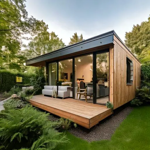
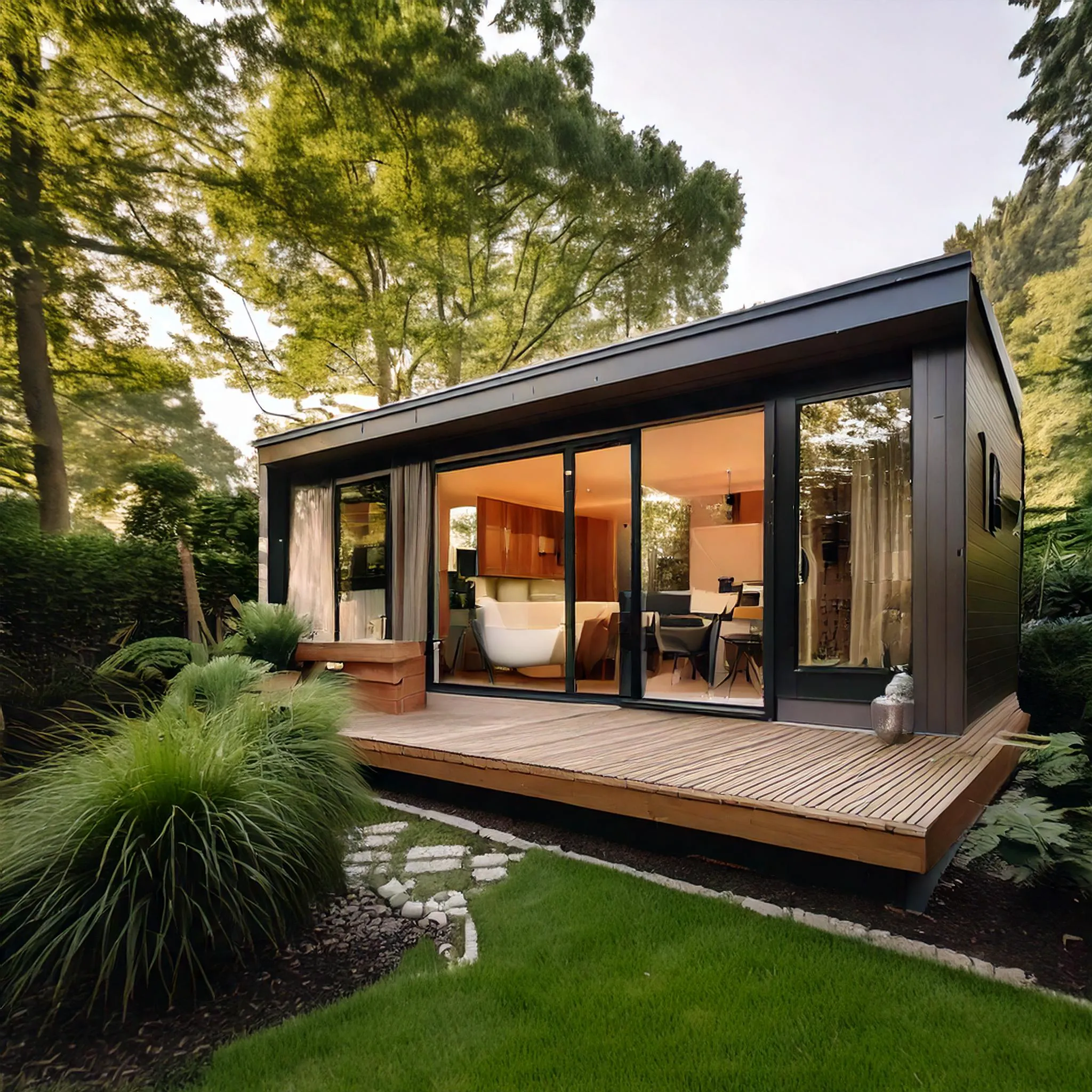
Most of our case studies are about what a garden room is. This one is about a number. The customer came to us wanting as much interior headroom as they could possibly get, and they were willing to spend what it took to get it. They also refused to trade away build quality or insulation to do it. Those two goals pull in opposite directions, which is what made this project worth writing about.
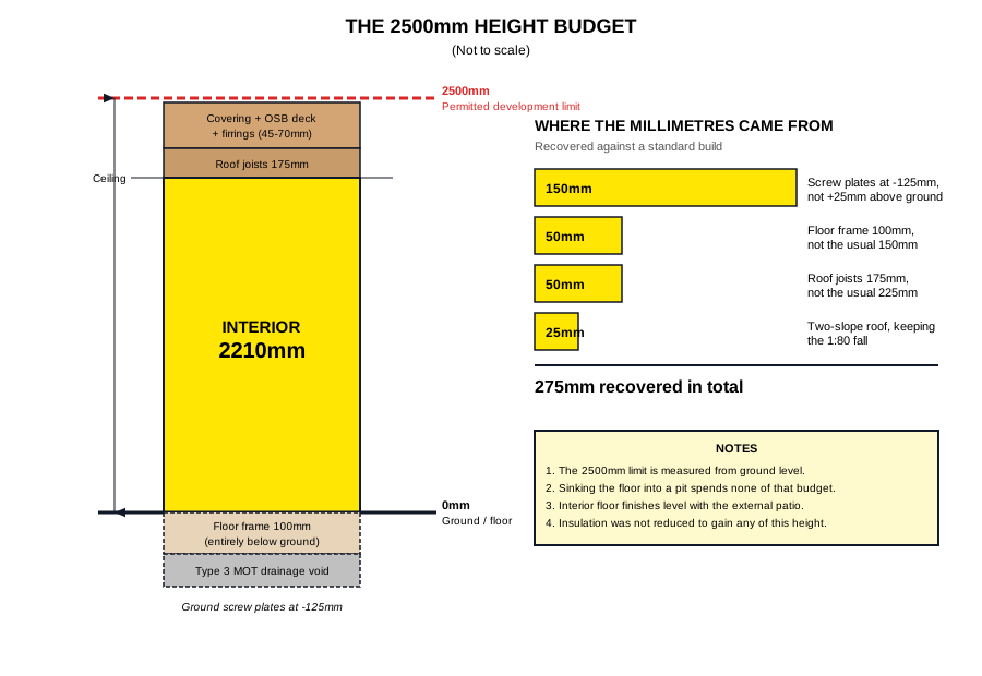
Permitted development allows an outbuilding up to 2.5m tall measured from ground level. That is the whole budget. Everything has to fit inside it: the floor structure, the ceiling, the roof joists, the fall on the roof and the roof covering. On a small room this can still allow for reasonable space. On a bigger one it's a real problem, because a longer span needs deeper joists, and every millimetre of joist depth comes straight off the ceiling height.
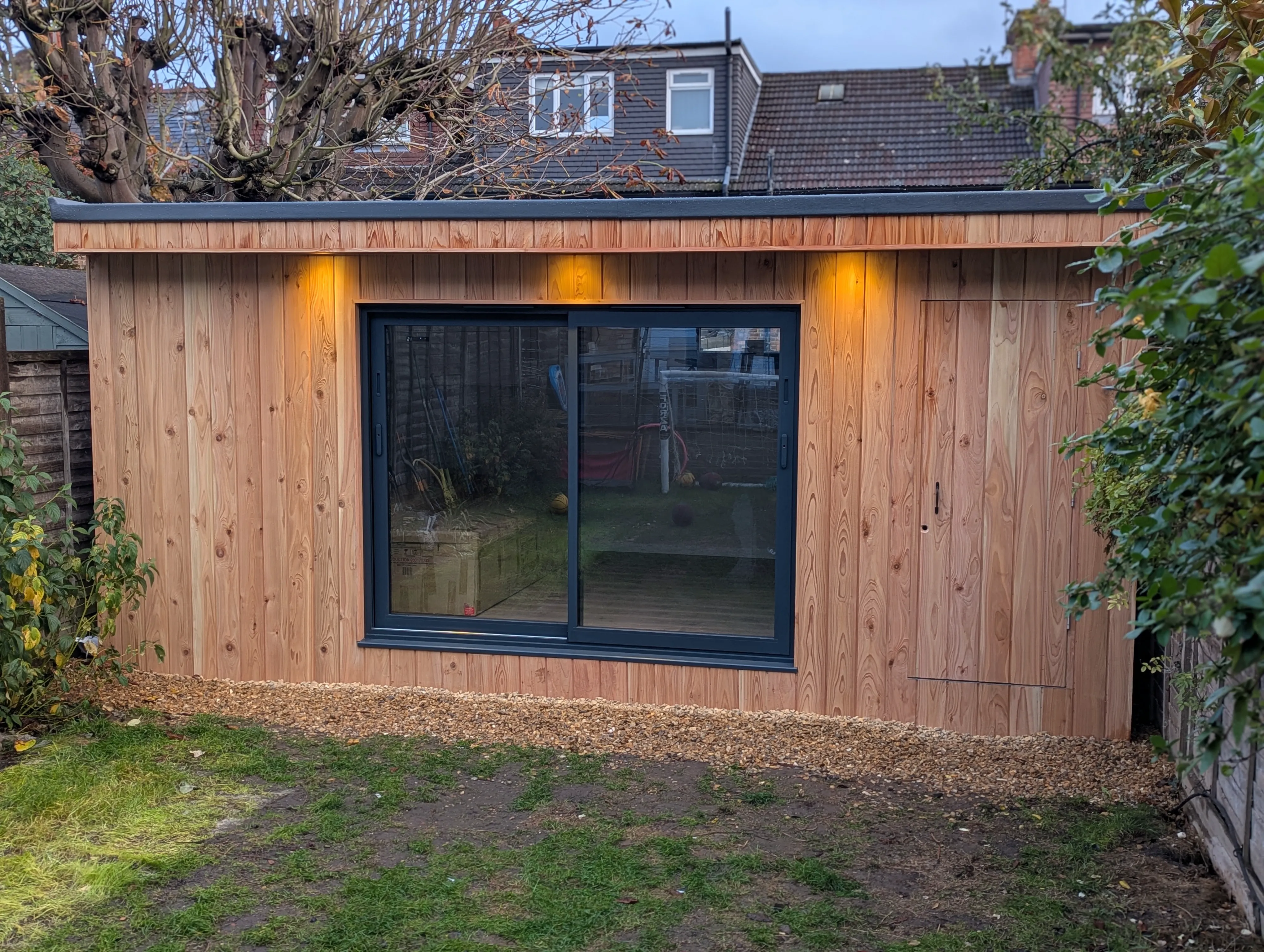
This build is 7.3m by 4.8m externally, sized to keep the internal floor area just below the 30m² threshold at which building regulations approval kicks in. It is, in other words, about as large as a garden room gets before it stops being a garden room - and therefore about the worst possible case for headroom.
We finished with a 2210mm ceiling, while also keeping it extremely well insulated. Here is how we achieved that.
First, We Went Downwards
The 2.5m limit is measured from ground level. It says nothing about what you do below ground level. So the cheapest millimetres available are the ones you dig for.
We designed and commissioned an excavation pit covering the entire footprint of the building, around 300mm deep. The bottom half was filled with MOT Type 3 aggregate, laid over a geotextile membrane and deliberately left uncompacted. That last detail matters and it is the opposite of what you would normally do with a sub-base. This aggregate is not there to carry load - the ground screws do that. It is there to hold open a void that soil cannot fill, so rainwater has somewhere to go and it doesn't flood the floor frame which is underground as well. Type 3 is graded with fewer fines than Type 1, so it holds more empty space between the chips, and compacting it would destroy the very thing it was laid for. It leaves roughly 3m³ of drainage void under the building.
Around the perimeter we set concrete lintels as retaining walls. These carry nothing structural either. Their job is simply to stop the surrounding soil from slumping back into the pit over the years and quietly filling in the space we had just paid to dig. They were finished with patio paving laid all around the pit.
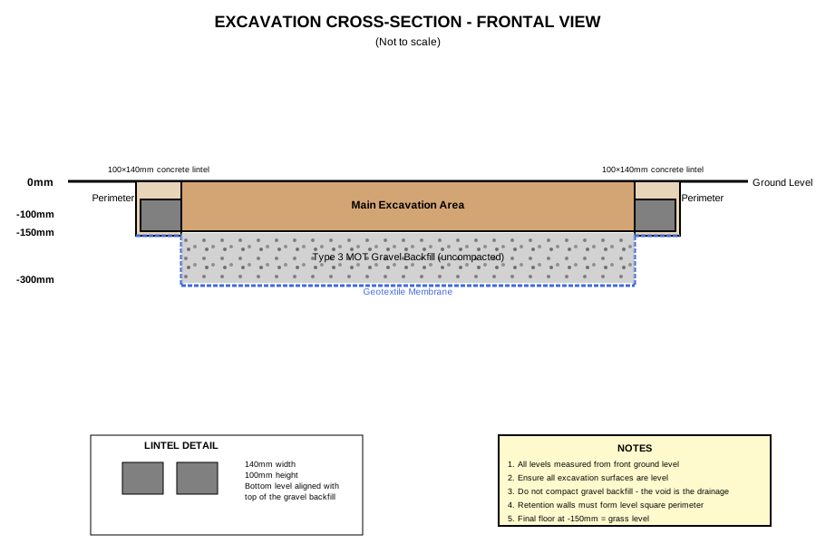
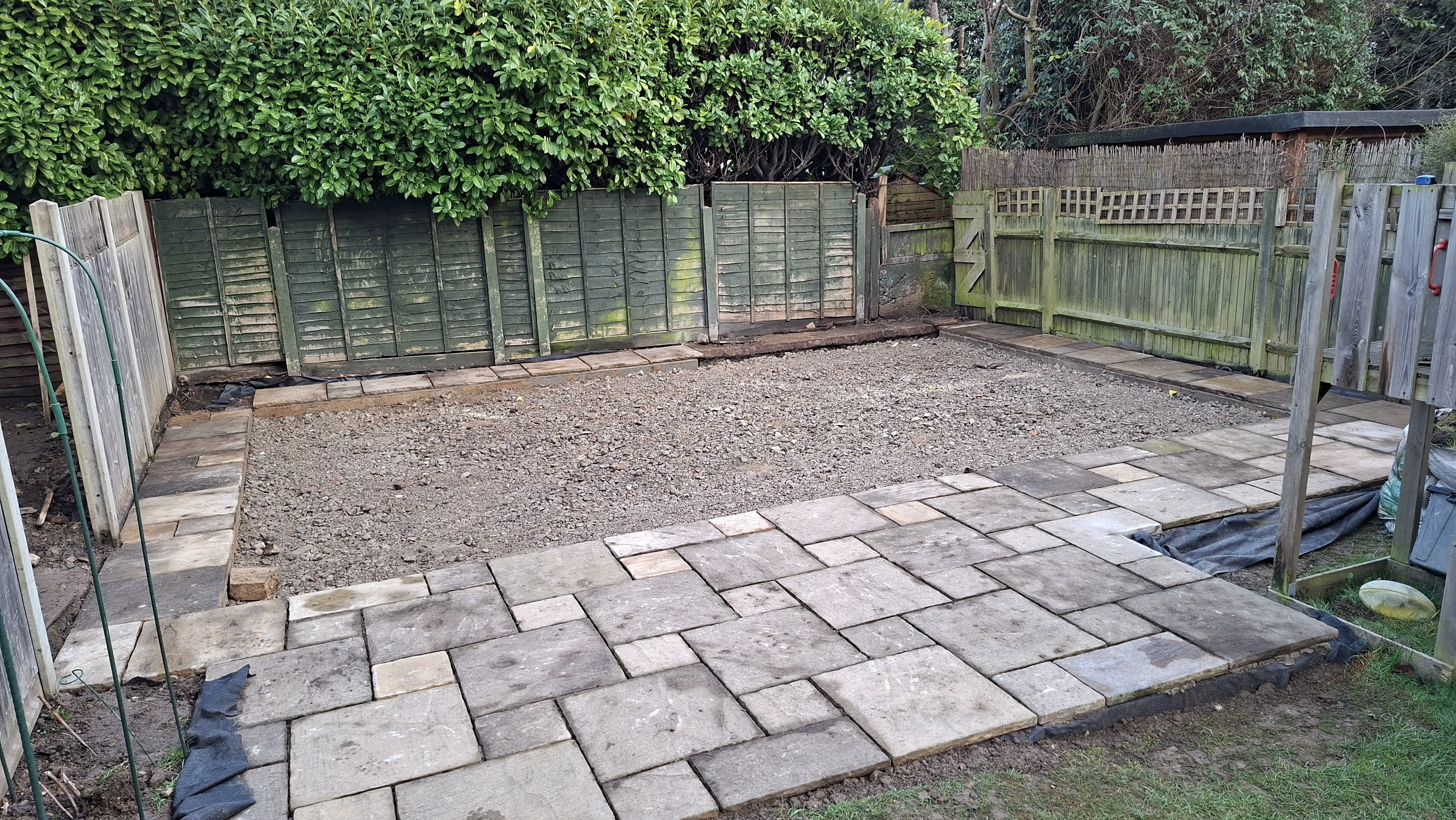
The ground screws then went into the pit with their base plates 125mm below ground level. In a normal build those plates sit around 25mm above it. That 150mm swing is the biggest single win in the project. The groundwork is involving and messy, but it if you want to achieve maximum headroom - it is worth.
A Floor Frame With Nowhere to Go
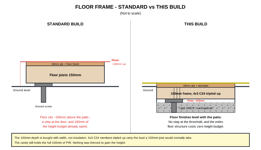
Sinking the screws only helps if the floor frame is shallow enough to sit in the space we made. Our standard floor frame is 150mm deep. For this build we designed one at 100mm.
You cannot simply make a joist shallower and hope. A timber joist gets its stiffness overwhelmingly from its depth, so removing 50mm removes a great deal more strength than it sounds like. We bought that strength back with width instead, using 4x3 C24 timber tripled up and bound together into single structural member where the loads demanded it. More timber, more labour, more cost - and the same load carried at two thirds of the depth. The cavity still takes the full 100mm of PIR, exactly as it would have at 150mm.
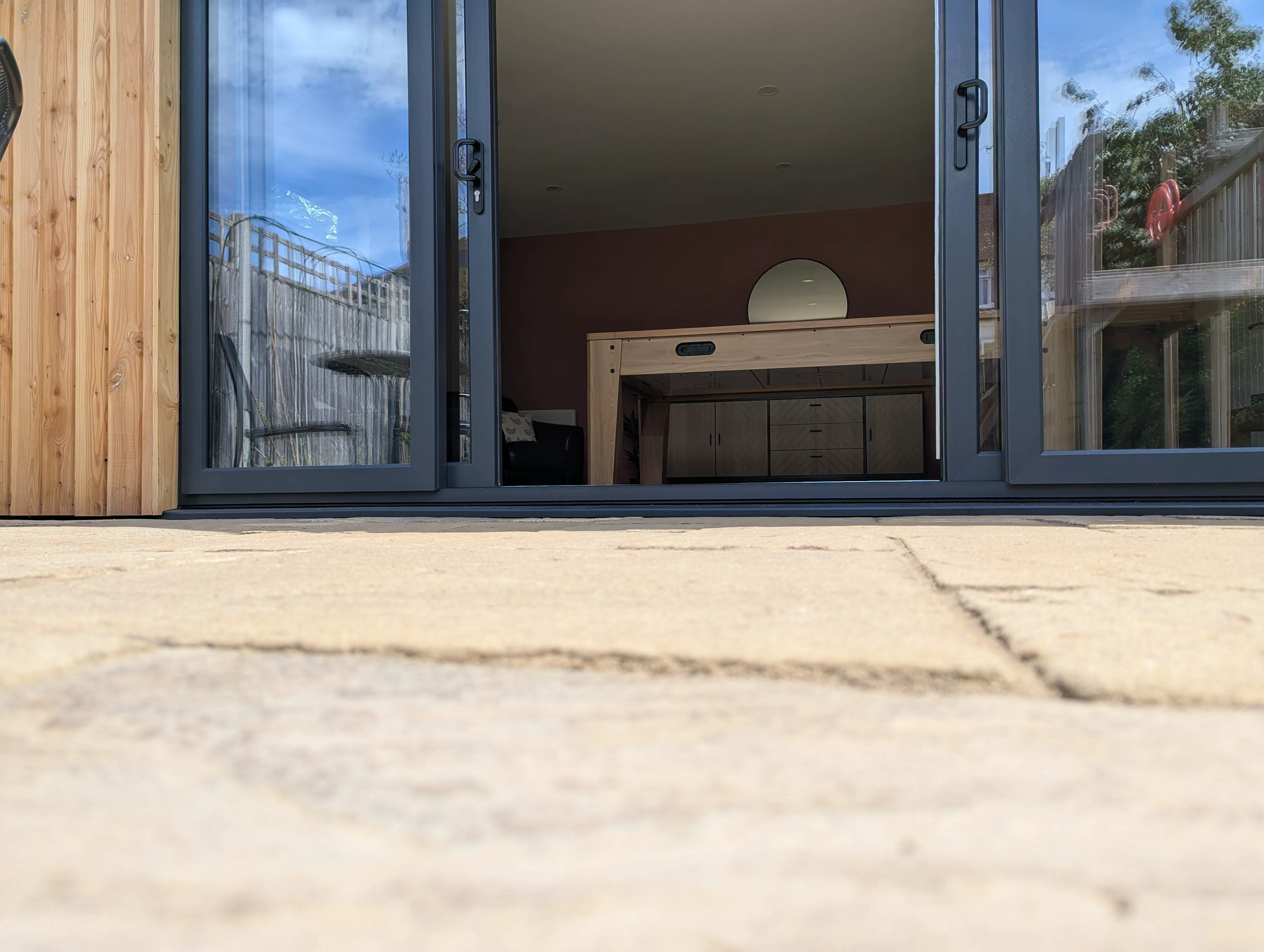
With the plywood subfloor and the laminate on top, the finished interior floor came out level with the external patio. That was the point of the exercise - but it also gave the customer something they had not asked for. There is no step at the door.
Trading Spacing for Depth in the Roof
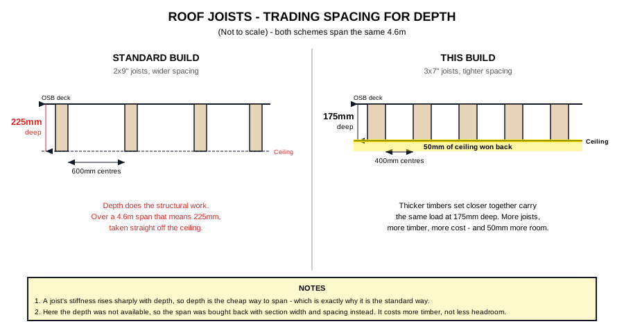
The roof joists span a little over 4.6m, which is a long way for a garden room. The standard answer for this span is 2x9" joists at 225mm deep, and that is the standard answer for a good reason: depth is by far the cheapest way to span a distance in timber.
Depth was the one thing we did not have. So we ran the same trade as the floor, in the other direction: 3x7" joists at 175mm deep, set at 400mm centres instead of the usual spacing. Thicker sections, more of them, closer together. It is a more expensive roof by some margin, and it hands back 50mm of ceiling.
Two Slopes Instead of One
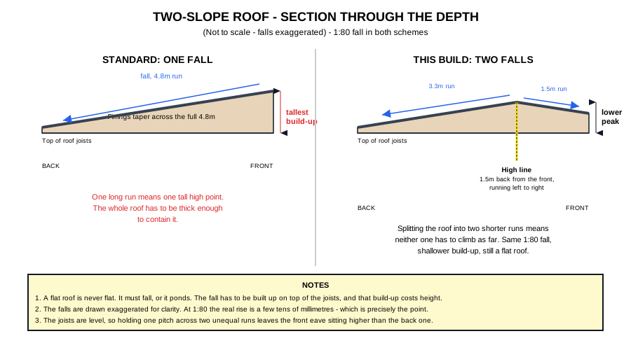
A flat roof is never actually flat. It has to fall, or water sits on it. That fall is built up in firring strips on top of the joists, and the build-up eats height at the high end. Across 4.8m of depth, even a gentle 1:80 fall has to climb a surprising amount by the time it reaches the far side.
So we split it. Rather than falling continuously from one edge to the other, the roof runs up to a high line set 1.5m back from the front and running left to right, then falls away in both directions. The pitch itself never changes - it stays at 1:80, and it is still very much a flat roof. But neither run has to climb as far as a single 4.8m run would, which takes another 25mm or so off the thickest part of the build-up.
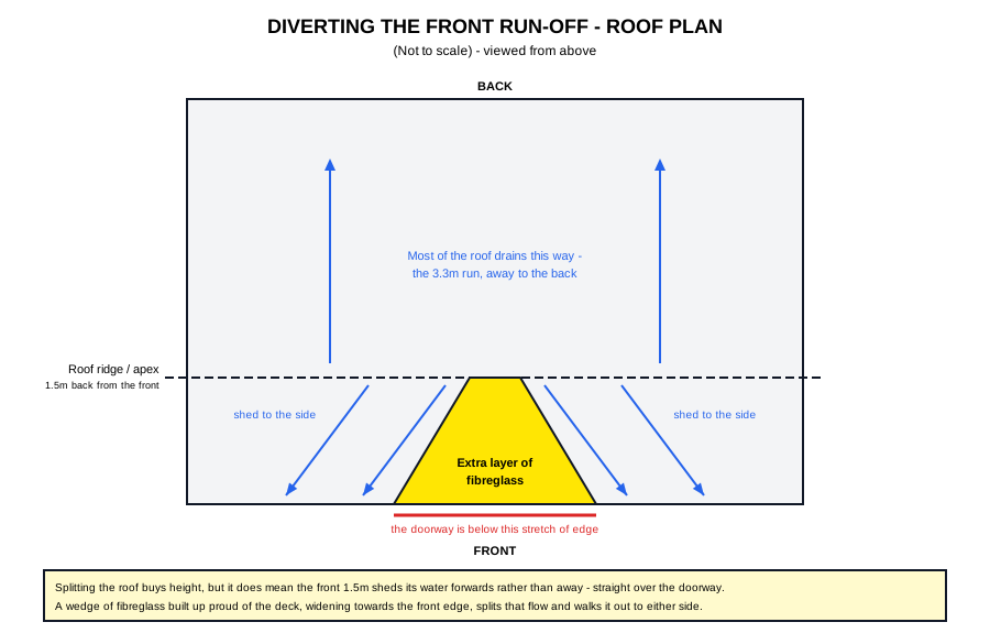
This means that some small amount of rainfall is actually flowing towards the front of the building, but we accepted that as a reasonable trade-off. We also added a small extra layer of fibreglass to divert the water away from the front door.
The Flitch Beam Over the Doors
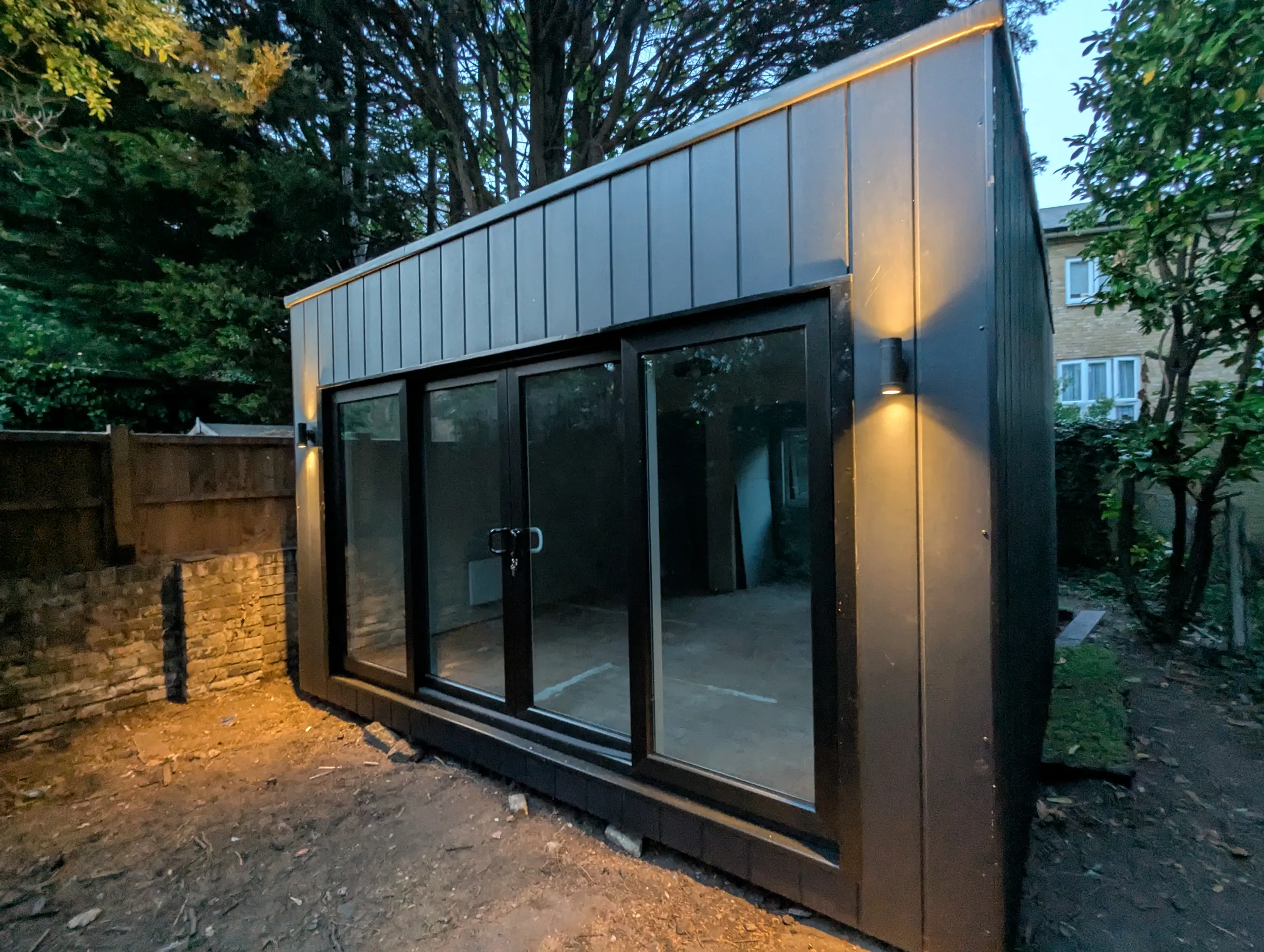
The best detail in this build is one you cannot see at all. The customer wanted a wide opening at the front: a sliding door with side lights, 3.4m across in total, and as tall as we could make it.
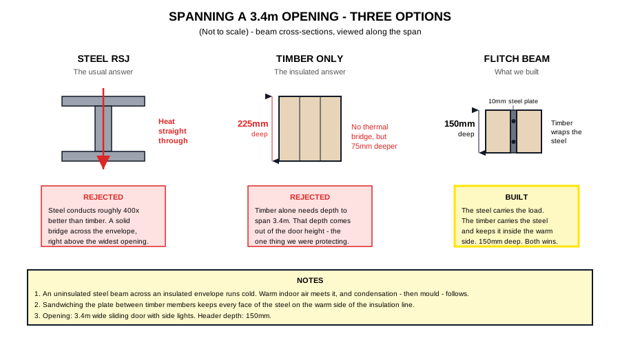
To span an opening that wide you would normally drop in a rolled steel joist. It works, it is well understood, and on this building it would have been a serious mistake. Steel conducts heat hundreds of times better than timber. An uninsulated steel beam laid across an insulated envelope is a thermal bridge in the most literal sense - a cold strip running the full width of the wall, right above the largest opening in the building. Warm, humid indoor air finds it, condenses on it, and mould follows. On a build where the entire point was uncompromised insulation, that was not a trade we were willing to make.
The alternative is an all-timber beam, but at 3.4m that means going to around 225mm deep - and 225mm of header depth comes straight out of the door height we were trying to protect.
So we used a composite flitch beam: a 10mm steel plate sandwiched between two timber members and bolted through. The steel does the structural work. The timber carries the steel and, more importantly, keeps every face of it on the warm side of the insulation line. The result spans 3.4m on a header just 150mm deep, with no thermal bridge anywhere in it.
The Result
Excavating for the screws found 150mm. The floor frame found 50mm. The roof joists found another 50mm. The two-slope roof found 25mm. Together that is roughly 275mm of ceiling that a conventionally built room of this size would simply not have had.
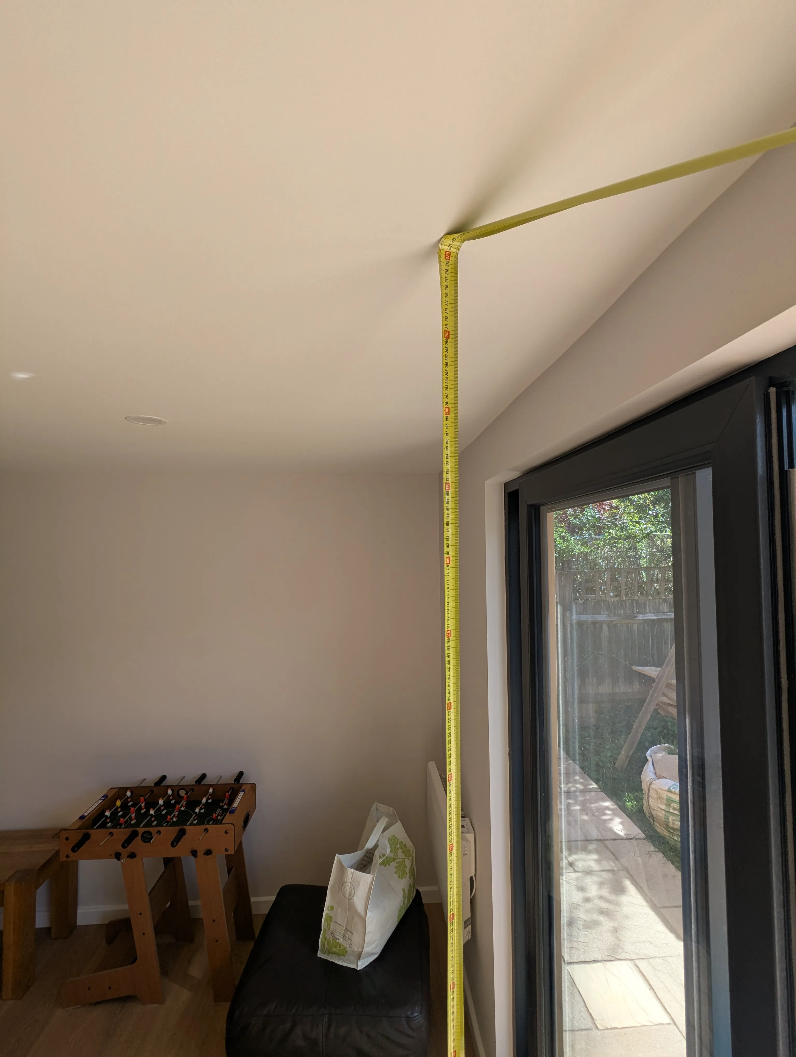
The finished interior ceiling height is 2210mm, inside a building that measures under 2500mm to the top of its roof. We went back with a tape measure to check, because a claim like that is worth checking.


None of It Came Out of the Insulation
This is the part that matters most, because it would have been very easy to find those millimetres the lazy way. Thinner insulation is the first thing to go when height gets tight. It went nowhere on this build:
- Roof: 150mm rigid PIR between the joists in a ventilated cold roof build-up - 0.16 W/m²K
- Walls: 100mm rigid PIR in the frame cavity, plus a further 50mm of rigid PIR across the outside of the frame to break the thermal bridging through the studs - 0.16 W/m²K
- Floor: 100mm rigid PIR in the frame cavity - 0.25 W/m²K
The 50mm layer over the outside of the wall frame is worth dwelling on, because it is the reason the walls perform as well as the roof despite holding less insulation. Timber studs conduct heat far better than the PIR sitting between them, so in an ordinary wall every stud is a small thermal bridge repeating every few hundred millimetres. Wrapping the whole frame in a continuous layer of rigid insulation cuts every one of those bridges at once. It also, incidentally, is why the as-built building came out 100mm wider and deeper than the groundwork drawings called for.
The cold roof deserves a note too, since a ventilated roof needs a clear air path above the insulation to work. The firrings that create the two falls sit on top of the joists and lift the deck clear of the PIR, leaving a void that varies between roughly 45mm and 70mm along the run. With a single ventilated run of 4.6m, that is comfortable. The firrings ended up doing two jobs at once: shaping the roof and ventilating it.
Was It Worth It?
Honestly, this was an expensive way to build a garden room. Excavating a pit, tripling up floor timbers, over-speccing the roof joists, fabricating a flitch beam - every one of those decisions costs real money, and none of them shows up in a photograph. A customer who wanted a straightforward room would not spend any of it, and we would not suggest they should.
But this customer knew exactly what they were buying, and what they bought was a room that does not feel like an outbuilding. It feels like a room in a house. That difference is 275mm, and 275mm turned out to be worth a great deal to them.
Got a Constraint of Your Own?
A height limit, an awkward plot, a slope, a boundary in the wrong place - the interesting projects usually start with something in the way. Tell us what yours is.